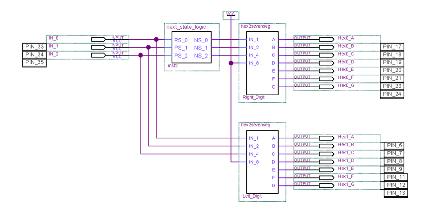
Top Level Design Showing Pin Assignments for UP2
The left seven segment display shows the present state, and the right one shows the next state. Switches 6, 7, and 8 correspond to PS2, PS1, and PS0 respectively.
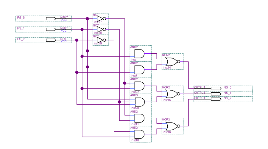
next_state_logic Module
Both the inputs and the outputs are inverted compared to the solution previously given for Assignment 2. This circuit uses “don’t” care” values for the next state when the present state is 1112.