Introduction
This exercise is to do a timing analysis of the single-cycle datapath for the MIPS processor developed in the book. For each of the instruction classes, R-type, Branch (beq and bne), Jump, and Memory (lw and sw), you are to determine how much time is required from the moment a new address is loaded into the program counter (PC) until it is safe to load the address of the next instruction.
Because the timing is different for lw and sw, they have to be analyzed separately, giving five different analyses that you will perform.
After you complete the analyses, you are to determine the maximum allowable clock frequency for the processor.
Remember, the purpose of this assignment is to help you to understand the course material. You can get away with handing in someone else’s work, but if you do not learn how to do the analyses yourself, you will not be able to answer exam questions about them.
The Assignment
| Element | Time Delay |
|---|---|
| Wires; bit concatenation, etc. | 0 ps |
| Individual gates | 2 ps |
| Multiplexers | 5 ps |
| Control logic; ALU control | 30 ps |
| Read a new value from a single register (the PC) | 20 ps |
| Read values from the register file | 75 ps |
| Write a value into the register file | 75 ps |
| 32-bit parallel adder | 60 ps |
| ALU | 100 ps |
| Read or write any memory | 150 ps |
Here is Figure 4.24 of the textbook, marked up with letters identifying various points in the datapath:
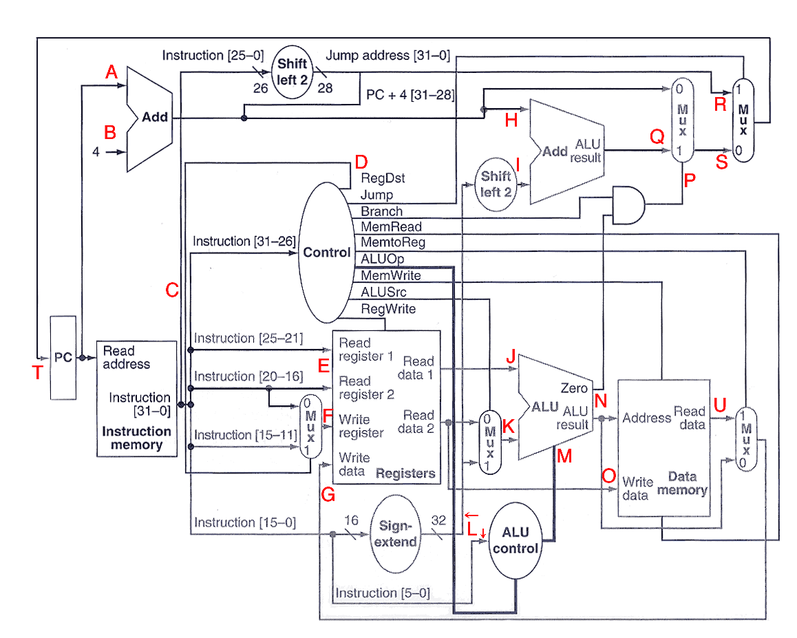
There are a few things to note about this figure:
- The textbook implements the beq, but not the bne instruction, so the logic for deciding whether to branch or not is simpler than what we did in class. Base your analyses on Figure 4.24, not on what we did in class.
- The textbook uses two 2×32 multiplexers for computing the next instruction address, and they are in the upper right section of the figure. In class, we combined these two into one 4×32 mux (and drew it to the left of the PC). Again, base your analyses on Figure 4.24, not what we did in class.
- The letter L is used to identify two different wires that appear to have different sources, but they always are valid at the same time because we are saying that the sign extension logic introduces no propagation delays.
- The top data input to the mux going into the ALU does not to have a letter because it is valid at the same time as J.
- D refers to all the outputs of the main control unit.
- N is for both outputs of the ALU.
Download and print a copy of the worksheet for this assignment:
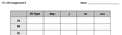 ,
and fill it in for the
five instruction types listed. Put in the time at which each point in the datapath that is used by
that instruction type would become valid. For example, R-type instructions do not use data memory, so
you would not fill in values for O or U.
,
and fill it in for the
five instruction types listed. Put in the time at which each point in the datapath that is used by
that instruction type would become valid. For example, R-type instructions do not use data memory, so
you would not fill in values for O or U.
Draw a circle around each value that is on the critical path for that instruction type.
For tmax, put in the time at which it would be safe for the next clock pulse to occur for each type of instruction. For the PC, the register file, and data memory, assume there is no problem applying the next clock pulse to the datapath as soon as the inputs to those elements are stable. In other words, assume it is safe to overlap the actual writing to these elements with the processing of the next instruction.
Circle the maximum tmax, and then fill in the value for Fmax, the maximum clock frequency that could be used.